Crest Audio X-VCA Manuel d'utilisateur
Naviguer en ligne ou télécharger Manuel d'utilisateur pour Mélangeurs audio Crest Audio X-VCA. Crest X-VCA Manual Manuel d'utilisatio
- Page / 142
- Table des matières
- MARQUE LIVRES
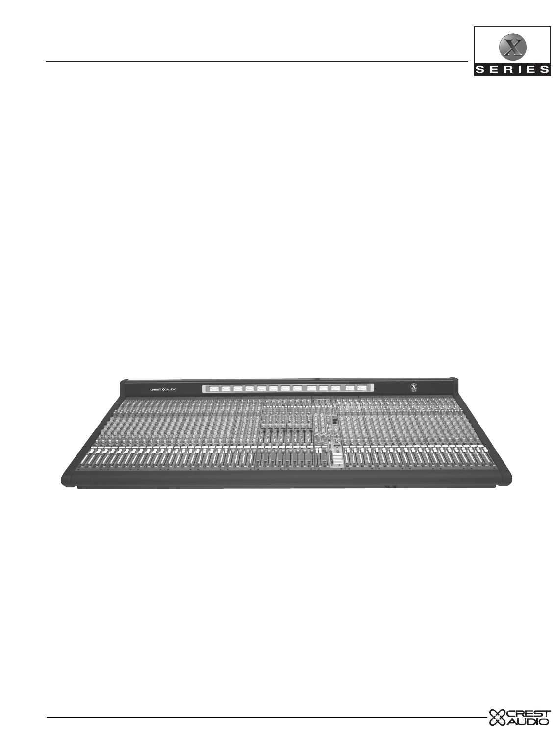
- X-VCA mixing consoles 1
- X-VCA block diagram 2
- Aux masters 3
- Mic and line inputs 3
- Control Icons 5
- SOLO LEFT 10
- SOLO RIGHT 10
- AFL MODE 10
- It's typical to 11
- Post fader when driving 11
- EQ features 13
- Many microphones 15
- Insert features 17
- Occasional flashing of the 19
- X-VCA STEREO INPUT 20
- (4 NORMALLY FITTED) 20
- If the channel's 21
- Left/Right signal goes 21
- LCR button is down 21
- AUX SENDS 22
- When VCA faders 23
- HPF but before the eq 25
- X-VCA MASTER MODULE 42
- TO EXT MTX 44
- X-VCA GROUP OUTPUT 50
- (1 OF 8 SHOWN) 50
- PAN control to 51
- Expansion 54
- GROUP output signal. see— 57
- SELECT A 58
- CHANNEL 58
- TO ASSIGN 58
- TER MODULE 62
- Output EQ features 63
- LEDLEDLEDLEDLEDLEDLEDLED 65
- MUTE MUTE 70
- EXTERNAL 74
- PGM INPUT 74
- ALTERNATE OUT 76
- (LOWER AREA) 78
- MICRO MUTE CONTROL 80
- SOLO CONTROL & STATUS 82
- 5-BAND SEMI-PARAMETRIC EQ 84
- X-VCA owner’s manual 100
- Inputs and outputs 106
- Solo - VCA edit switch 129
- SAFETY CONSIDERATIONS 141
Résumé du contenu
owner’s manual X-VCA mixing consoles(PRELIMINARY COPY)
1p. 10X-VCA owner’s manual mono input modulemodulepanelPREPREAUXPRE5-6347-8124012606•320+–4012606•320+–40201006•330+–40201006•330+–40201006•330+–40201
p. 100X-VCA owner’s manual 6microprocessor controlmute control paneltypical input or output
p. 101microprocessor control6The Safe SceneThere may be occasions when a channel needs to be made "Safe" from all pro-grammed mutes.This may
p. 102X-VCA owner’s manual 6microprocessor controlmute control paneltypical input or output
UtilitiesThe Mute Controller has a number of parameters that the user can change. A UtilityMode is provided for accessing these settings.The following
p. 104X-VCA owner’s manual 6microprocessor controlmute control paneltypical input or output
Changing and reviewing the utility changesThe Utility settings can be accessed by entering Utility Mode. Once there, the differ-ent parameters can be
p. 106X-VCA owner’s manual vca facilities7Inputs and outputs LCR1234567812345678PKSIGLRMUTEVCA1MUTEVCA2ML-RPAN ONGROUPSML-RBAL ONGROUPSPK–60SIG+851005
p. 107vca facilities7X-VCA operation - overviewIn addition to Mute scenes, the X-VCA Micro also controls the VCA assignment foreach Channel.A Channel
p. 108X-VCA owner’s manual vca facilities7Inputs and outputs LCR1234567812345678PKSIGLRMUTEVCA1MUTEVCA2ML-RPAN ONGROUPSML-RBAL ONGROUPSPK–60SIG+851005
VCA assigning - overviewThere are two methods available for assigning Channels to the 8 VCA Masters; thefirst method views the assignment from the Cha
p. 11mono input module1aux send featuresEight auxiliary sends are available for creating individual output mixes. These canbe used to drive effects pr
p. 110X-VCA owner’s manual vca facilities7Inputs and outputs LCR1234567812345678PKSIGLRMUTEVCA1MUTEVCA2ML-RPAN ONGROUPSML-RBAL ONGROUPSPK–60SIG+851005
p. 111vca facilities7VCA assigning - overviewVCA Assignment- Scene-to-Scene changes:When operating the X-VCA in VFS Mode, up to 128 different VCAassig
p. 112X-VCA owner’s manual vca facilities7Inputs and outputs LCR1234567812345678PKSIGLRMUTEVCA1MUTEVCA2ML-RPAN ONGROUPSML-RBAL ONGROUPSPK–60SIG+851005
p. 1137VCA assignment 1 - detailed operationNote: Front Panel Switches are indicted by BOLD-HYPHENATED-CAPITALIZED-TEXT.For the 8 VCA Masters, the swi
p. 114X-VCA owner’s manual vca facilities7Inputs and outputs LCR1234567812345678PKSIGLRMUTEVCA1MUTEVCA2ML-RPAN ONGROUPSML-RBAL ONGROUPSPK–60SIG+851005
p. 1157VCA Safe ModeThe user can choose to "SAFE" a Channel from ALL its VCA Assignmentswhile in either VCA Edit Mode.This doesn’t actually
p. 116X-VCA owner’s manual vca facilities7Inputs and outputs LCR1234567812345678PKSIGLRMUTEVCA1MUTEVCA2ML-RPAN ONGROUPSML-RBAL ONGROUPSPK–60SIG+851005
VCA assignment 2 Detailed OperationThere are two methods for doing VCA Assign on the X-VCA.Note: Front Panel Switches are indicted by BOLD-HYPHENATED-
p. 118X-VCA owner’s manual vca facilities7Inputs and outputs LCR1234567812345678PKSIGLRMUTEVCA1MUTEVCA2ML-RPAN ONGROUPSML-RBAL ONGROUPSPK–60SIG+851005
p. 119VCA copyIt is possible to copy a VCA assignment from one Scene location to another. Copies can bemade between Scene-0 and any Sequenced Scene, o
1p. 12X-VCA owner’s manual mono input modulemodulepanelEQONFREQ1.51.5SHELFSHELFLFLMHMHF– +.73Q3K6K12K20K1K18K1.51K2K4K8K4006K1.5.73Q1K2K1001.520050040
p. 120X-VCA owner’s manual vca facilities7Inputs and outputs LCR1234567812345678PKSIGLRMUTEVCA1MUTEVCA2ML-RPAN ONGROUPSML-RBAL ONGROUPSPK–60SIG+851005
p. 121VCA Assignment - starting freshWhen creating an assignment list for a new show, it’s usually a good idea to clear out theassignments from the pr
p. 122X-VCA owner’s manual vca facilities7Inputs and outputs LCR1234567812345678PKSIGLRMUTEVCA1MUTEVCA2ML-RPAN ONGROUPSML-RBAL ONGROUPSPK–60SIG+851005
p. 123VCA Mute switchEach of the 8 VCA Masters has a Mute Switch associated with it.When this momentaryswitch is pressed, it will light steady RED and
p. 124X-VCA owner’s manual vca facilities7Inputs and outputs LCR1234567812345678PKSIGLRMUTEVCA1MUTEVCA2ML-RPAN ONGROUPSML-RBAL ONGROUPSPK–60SIG+851005
VCA Master Solo/Assign switchEach of the 8 VCA Masters has its own SOLO switch.This switch has 2 functions-Solo andAssign:VCA Assign: When in Edit Cha
p. 126X-VCA owner’s manual vca facilities7Inputs and outputs LCR1234567812345678PKSIGLRMUTEVCA1MUTEVCA2ML-RPAN ONGROUPSML-RBAL ONGROUPSPK–60SIG+851005
VCA channel soloSolo operation of a Channel assigned to multiple VCA Groups:It is possible for a Channel to be assigned to more than one (up to 8 poss
p. 128X-VCA owner’s manual Solo - VCA edit switch 8Inputs and outputs LCR1234567812345678PKSIGLRMUTEVCA1MUTEVCA2ML-RPAN ONGROUPSML-RBAL ONGROUPSPK–60S
Solo - VCA edit switchThroughout the X-VCA console, Stereo Solo/VCA edit switches can befound on just about every input and output.The Solo - VCA edit
p. 13mono input module1EQ featuresMany audio signals coming into the console require some degree of corrective eqin order to be part of a good soundin
p. 130X-VCA owner’s manual dynamics control9
X-VCA dynamics controlIntroductionThe X-VCA includes a number of features for control of signal dynamics in both theAudio Group and Master sections. I
p. 132X-VCA owner’s manual dynamics control9
p. 133Group section: Compressor/Limiter functionsThe gate and compressor functions affect all signals summed into their respective Audio Groupbuses. A
p. 134X-VCA owner’s manual dynamics control7
group section: gate functionsEach Audio Group also incorporates a "noise gate" function. In live sound applications, thisfeature is most com
p. 136X-VCA owner’s manual dynamics control7
p. 137output limiter functionsThe X-VCA provides output limiters inserted in the main output circuits following the L/RStereo and Mono master faders.T
p. 138X-VCA owner’s manual power supply8model 5A power supplyMatrix 4 Matrix 3 Matrix 2 Matrix 1MIDIIn OutDC InInsertSendReturnMonoOutAssist Out Alt R
p. 139power supply usageconsole and power supply groundingConsole chassis ground is electrically connected to: the audio ground, pin-1 of XLR connecto
1p. 14X-VCA owner’s manual mono input modulemodulepanel20 4004080200EQONFREQSHELFHPFPANINSERTONC– +4008004060010 0200.73block diagramGCLEVELFREQQLEVEL
p. 140model 5A power supplyspecifications+18V @ 5A DC-18V@ 5A DC+12V @ 4A DC+48V @ 0.75A DCtwo Hirose JR16RK-7S connectors on rearconnector meets JIS
p. 141power supply usagesupply identificationThe type of power supply can be identified by the model number shownon the back of the chassis and panel
v.1.1 01/25/01
p. 151high-pass filter—HPF Proper use of the high-pass filter reduces or eliminates unwanted low frequencieswithout substantially affecting the progra
1p. 16X-VCA owner’s manual mono input modulemodulepanel20 4004080200EQONFREQHPFODD - LR - EVENPANINSERTONSAFEPREVIEWC– +80040600block diagramGCGCFOUR-
p. 17mono input module1Insert featuresInsert ON switch The Insert point is located after the EQ and before the Low Pass Filter.External signal proces
1p. 18X-VCA owner’s manual mono input modulemodulepanelLCR12345678ML-RPAN ONGROUPSPK–60SIG+851005102030155040SOLOVCAASSIGNblock diagramFOUR-BAND FULLY
p. 19mono input modulelevel meter featureslevel meterEach input includes a five-segment LED meter for visu-ally monitoring signal levels.This is essen
X-VCA owner’s manual X-VCA block diagramVCA SUB-CARDGCGCX-VCA MASTER MODULE (LOWER AREA)MASTERMICROINTER-FAC ECARD-INPUT &GROUPCONTROLTORIGHTSIDE-
1p. 20X-VCA owner’s manual mono input modulemodulepanelODD - LR - EVENPANMUTESAFEPREVIEWCLCR12345678ML-RPAN ONGROUPSPK–60SIG+851005102030155040SOLOVCA
bus assignment featuresThe Input bus assignment section offers considerable flexibility for creating whateventually becomes the main output mix. Such
p. 22X-VCA owner’s manual mono input module1modulepanelLCR12345678ML-RPAN ONGROUPSPK–60SIG+851005102030155040SOLOVCAASSIGNblock diagramVCA SUB-CARDVCA
p. 23mono input moduleWhen VCA fadersbecome dirty or worn,they do not become noisybecause there's no audiogoing through them.+1featuresinput fade
block diagram1p. 24X-VCA owner’s manual mono input modulemodule rearDirectOutDirectOutDirectOutDirectOutBal Line In Bal Line In Bal Line In Bal Line I
2p. 25mono input modulerear panel featuresdirect out 1/4" TRS jackThe input channel's signal is available at this output jack.The default si
2p. 26X-VCA owner’s manual stereo input moduleGAINPREPREAUX12345678PKSIGLRODD - LR - EVENBALSTEREO INPUTMUTESAFEPREVIEW=HPF20 4004080200EQONPRE5-6347-
2p. 27stereo input modulefeaturesThe Stereo Input Module can be configured to accept either a stereo pair of sig-nals or a standard mono signal. Unlik
p. 28stereo input module2X-VCA owner’s manual GAINPREPREAUX12345678PKSIGLRODD - LR - EVENBALSTEREO INPUTMUTESAFEPREVIEW=HPF20 4004080200EQONPRE5-6347-
2p. 29stereo input modulefeaturespolarity reverse—øThis switch inverts the polarity of the right input signal in relation to the left inputsignal. see
12345group module p. 43VCA groups, audio groups, dynamics, matrix andAux mastersleft, right & mono p. 59mastersmaster control section p. 716microp
2p. 30stereo input moduleX-VCA owner’s manual GAINPREPREAUX12345678PKSIGLRODD - LR - EVENBALSTEREO INPUTMUTESAFEPREVIEW=HPF20 4004080200EQONPRE5-6347-
2p. 31stereo input moduleaux send featuresRefer to the Mono Input Module for basic information on the Aux sends.What'scovered here is information
p. 32stereo input module2X-VCA owner’s manual GAINPREPREAUX12345678PKSIGLRODD - LR - EVENBALSTEREO INPUTMUTESAFEPREVIEW=HPF20 4004080200EQONPRE5-6347-
2p. 33stereo input moduleEQ featuresThe X-VCA Stereo Input module offers four bands of EQ - High, High mid, Lowmid and Low.The High and Low are shelvi
p. 34stereo input module2X-VCA owner’s manual GAINPREPREAUX12345678PKSIGLRODD - LR - EVENBALSTEREO INPUTMUTESAFEPREVIEW=HPF20 4004080200EQONPRE5-6347-
2p. 35stereo input modulemetering featuresBalance controlSee description of Bus Assignment features later in this sectionsafe previewSafe Preview LEDS
p. 36stereo input module2X-VCA owner’s manual GAINPREPREAUX12345678PKSIGLRODD - LR - EVENBALSTEREO INPUTMUTESAFEPREVIEW=HPF20 4004080200EQONPRE5-6347-
2p. 37stereo input moduleBus assignment featuresBalance controlThe Balance control adjusts the Stereo balance for the Left/Right assignmentand Group a
p. 38stereo input module2X-VCA owner’s manual GAINPREPREAUX12345678PKSIGLRODD - LR - EVENBALSTEREO INPUTMUTESAFEPREVIEW=HPF20 4004080200EQONPRE5-6347-
2p. 39stereo input modulefeaturesinput faderThe input fader is the primary level control for signals being sent to any of theconsoles mix buses.The si
p. 40X-VCA owner’s manual stereo input module2Bal Line In 2 Bal Line In 2 Bal Line In 2 Bal Line In 2LRLRLRLRBal Line In 1 Bal Line In 1 Bal Line In 1
p. 41stereo input module2rear panel featuresThe stereo line-input module provides connectors for three stereo line-level sig-nals. see—line 2 switch.b
p. 42group module3X-VCA owner’s manual module panelSOLOSAFEPREVIEWAUX 1–2STEREO PAIRINPUT SENDSLEVPANOUTPUTLEVSOLOTALKTOMUTESAFEPREVIEWOUTPUTLEVAUX2TA
p. 43group module3group module featuresThe Group modules are physically configured in pairs, four pairs making upthe eight Groups. Each of the eight G
p. 44group module3X-VCA owner’s manual module panelMATRIXSENDS12341234MATRIXSENDSMTX SENDSPOST GRP 1MTX SENDSPOST GRP 240201006•330+–40201006•330+–402
matrix sendsThe X-VCA includes four MATRIXoutputs. Each of these outputs can be made upof signals from the eight GROUPS; the left, right and mono buse
p. 46group module3X-VCA owner’s manual module panel3161220206THR(DBU)STEREOLINKGATECOMPRATIO(N:1)GAIN(DB)10–+354015150251–2GATE1420102RATIOTHR1:51:231
group dynamics sectionThe X-VCA Audio Group and Master modules include a number of featuresfor flexible dynamic control of signal levels. On Group mod
p. 48group module3X-VCA owner’s manual 3module panelMUTESAFEPREVIEWGRPATT(DB)VOXPERCAUTOSOFTKNEE12357912151821COMPGATELR=ONML-RGROUPASSIGNGROUPINSERTG
group dynamics sectionNote:The following dynamics controls are located adjacent to the Group fader.gate ON (downward expander) Activates the gate (dow
how to use this manualformatThis manual uses a format that is intended to be easy to read, yet technical for thosewho need to know all the details. Fo
p. 50group module3X-VCA owner’s manual 3modulepanelMUTESAFEPREVIEWGRPATT(DB)VOXPERCAUTOSOFTKNEE12357912151821COMPGATELR=ONML-RGROUPASSIGNGROUPINSERTGR
p. 51group module3audio group control featuresThis section provides standard features for the Group bus masters. Signals that areassigned to the Audio
p. 52group module3X-VCA owner’s manual 3modulepanelMUTEVCA1MUTEVCA251005102030155040UNITYVCA 1SOLOASSIGNEDITVCA 1ASSIGN51005102030155040UNITYVCA 2SOLO
VCA group master control featuresThis section controls VCA levels of any assigned input channels or audiogroups assigned to the VCA group.VCA control
p. 54group module3X-VCA owner’s manual 4Group Out3Group OutAUX4AUX3AU2InsertSendReturnInsertSendReturn Re8Group Out7Group Out6Group Out5Group OutAUX8A
p. 55group module3rear panel featureslamp dim Goose-neck lamps light-up at full intensity.Goose-neck lamps light-up at medium intensity.meter bridge
p. 56group module3X-VCA owner’s manual ∑GC∑GCVCAPKSIGOMEVULEOXTULERIBBONCABLEINTER-CONNECTMIX AMPTALK TO AUXAUXINSERT RTNAUXINSERTSEND RTNAUXMIXTB
p. 57group module3rear panel featuresgroup outputThis balanced male XLR connector carries the GROUP output signal. see—group fader, front-panel descri
p. 584X-VCA owner’s manual left / right & mono mastersmodulepanel401510010•520+–SOLOSAFEPREVIEWOUTPUTLEV401510010•520+–SOLOTALKTOMUTESAFEPREVIEWOU
4p. 59left / right & mono master modulesfeaturesAside from their Left / Right and Mono assignments, the X-VCA Left / Right andMono master modules
p. 6X-VCA owner’s manual mono input modulemodulepanelGAIN+48VPADLINEØ301220405072block diagramLEVELFREQQQFOUR-BAHHF400 3 - 0.71K - 20 KHZ3 - 0.7SHINPU
p. 604X-VCA owner’s manual left / right & mono mastersmodulepanel40201006•330+–40201006•330+–MATRIXSENDS40201006•330+–40201006•330+–MATRIXSENDS402
4p. 61left / right & mono master modulesmatrix sendsDue to space considerations, the Left Matrix sends are located on the Left / Rightmaster modul
p. 624X-VCA owner’s manual left / right & mono mastersmodulepanel1.5.73QHM3K6K12K20K1K18K1.51.5.73Q3K6K12K20K1K18K1.5HF HFHM1K2K4K8K4006K1K2K4K8K4
4p. 63left / right & mono master modulesOutput EQ featuresIndependent stereo and mono output EQ sections are provided on X-VCA.The EQconsists of 5
p. 644X-VCA owner’s manual left / right & mono mastersmodulepanelON1369121824MAX(DBU)OUTPUT LIMITEROUTPUT LIMITERL/R MONOLIMITON(RMS)LIMITON(RMS)6
Note: Caution shouldbe exercised if a sig-nificant amount of gainreduction is displayed, asthis may cause a deteriora-tion in overall sound quality. +
p. 664X-VCA owner’s manual left / right & mono mastersmodulepanelTALK TOMONOTALK TOL/RSUML/RL/R TOMONO510051020301550510051020301550PKSIGLRMEDITCH
p. 674output featuressum L/R switch (Left / Right module) Combines the Left and Right outputs into summed mono outputs.This feature is useful when onl
p. 684X-VCA owner’s manual left / right & mono mastersmodulepanelTALK TOMONOTALK TOL/RSUML/RL/R TOMONO510051020301550510051020301550PKSIGLRMEDITCH
4features100mm Left,Right and Mono fadersThese faders control the overall Left, Right and Mono master output levels. Notethat the Left, Right and Mono
p. 7mono input modulefeaturesphantom power +48V48 volts DC is applied to pins 2 and 3 on the mic-input XLR connector. Thisoption is used with condense
p. 70X-VCA owner’s manual 5master control sectionmodulepanel401510010•520+–SOLOSAFEPREVIEWOUTPUTLEV401510010•520+–SOLOSAFEPREVIEWOUTPUTLEVMUTE MUTEMTX
5p. 71master control sectionfeaturesThe Master control section offers some flexible signal routing solutions as well asutilitarian functions.Also incl
p. 72X-VCA owner’s manual 5master control sectionmodulepanel40201006•330+–40201006•330+–40201006•330+–40201006•330+–MATRIXSENDSMATRIXSENDS40201006•330
p. 735matrix sendsThe master control section contains two sets of Matrix sends.The first set is usedto dial the Mono master signal into the four matri
p. 74X-VCA owner’s manual 5master control sectionmodulepanel.7Q12K20K18KTB MLFHF0151588+–0151588+–401510010•520+–LEV4K8K6K.7Q2K4K3KSOLOPKSIGMONOL-RASS
p. 75master control section5external stereo program inputThe external stereo program input allows a line level stereo source to be fed intothe console
p. 76modulepanelSOLOSIG7QALT OUTMONOSOLOF135710092864135100264PRE FDRFROML/R/MTALKTOSUMMONOTALTOSUMON400800600QNFREQ– +IMITER62015MAX(DBU)6001.2K1K4DB
p. 77master control section5alternate output featuresAdditional outputs are available beyond matrix and headphone outputs.These outputs are derived fr
p. 78modulepanelSOLOALT OUTMONITOROUTSOLOOFF5710986135710092864PRE FDRFROML/R/MTALKTOSUMMONOTALKTOSUMMONOACK CTRL HEADPHONES571098611135710092864LEV L
p. 795alternate output featuresMonitor outThe Monitor out is very similar to the Alt out. Instead of assigning the Left andRight signals to the monito
p. 8X-VCA owner’s manual mono input module1modulepanelGAIN+48VPADLINEØ301220405072block diagramLEVELFREQQQFOUR-BAHHF400 3 - 0.71K - 20 KHZ3 - 0.7SHINP
p. 80X-VCA owner’s manual 5master control sectionmodulepanelSOLOALT OUTMONITOROUTSOLOOFF5710986135710092864PRE FDRFROML/R/MTALKTOSUMMONOTALKTOSUMMONOA
p. 815talkback and solo featurestalkback controlThe talkback section provides the facilities to take either an external input signal, oran internally
p. 82X-VCA owner’s manual 5master control sectionSOLOACTIVECLEARLCR TOOUTPUTSTBONPINKNOISESOLO CONTROLACK CTRL HEADPHONESTO LATCH)MONO TOON/PHONES5710
p. 835solo featuresThe X-VCA provides a powerful stereo solo system. Any input or outputcan be monitored pre (PFL) or after level control (AFL), as de
p. 84X-VCA owner’s manual 5master control sectionMatrix 4 Matrix 3 Matrix 2 Matrix 1MIDIIn OutDC InInsertSendReturnMonoOutAssist Out Alt R Out Alt L O
p. 85master control section5rear panel featuresmatrix expansion The X-VCA offers a matrix expansion system. In additional to the four matrixoutputs av
p. 86X-VCA owner’s manual 5master control sectionMASTERMICROINTER-FAC ECARD-INPUT &GROUPCONTROLTORIGHTSIDE-INPUTMICROCARDSTOLEFTSIDE-GROUPMICROCAR
p. 875rear panel featuresLeft, Right and Mono insert pointsSeparate send and return 1/4" TRS jacks are provided for inserting external signalproc
p. 88X-VCA owner’s manual 6microprocessor controlSINGLESCENEEDITPREVIEWMICROUTILITYEDITSAFEHEADPHONE AND TALKBACK JACKSLOCATED BELOW ARMRESTSEQUENCEDS
p. 896microprocessor controlmicroprocessor controlled mutingThe Crest X-Series of Consoles* is equipped with a micro-con-trolled Mute Controller which
p. 9mono input modulefeaturesgain The Input gain control range is closely related to the status of the PADswitch andthe LINE switch. In order to estab
X-VCA owner’s manual 6microprocessor controlmute control paneltypical input or output
p. 91microprocessor control6Mute controllerA)Up/DownEach press of these switches increments or decrements the Patch Display(B). Holding either button
p. 92X-VCA owner’s manual 6microprocessor controlmute control paneltypical input or output
p. 936microprocessor controlMute controllerI)Recall (Next)Each press of this switch increments the Sequenced Mutes by one, the dis-play (B) will refle
p. 94X-VCA owner’s manual 6microprocessor controlmute control paneltypical input or output
p. 956microprocessor controlchannel mute controlsJ)Status LEDThis bi-color LED, associated with each controlled Mute, shows the condi-tion of that mut
X-VCA owner’s manual 6microprocessor controlp. 96mute control paneltypical input or output
p. 97microprocessor control6mute scenesThere are 9 possible Scene sources: Manual Mute Scenes 1 thru 8, and theMicro Scene.The Micro Scene button (G)
p. 98X-VCA owner’s manual 6microprocessor controlmute control paneltypical input or output
p. 99microprocessor control6copying a mute sceneCopying a Mute Scene:Mute Scenes can be copied from a Sequenced Scene (Patch) to a Manual MuteScene. M
Produits connexes et manuels pour Mélangeurs audio Crest Audio X-VCA
 (11 pages)
© 2020, manymanuals.fr. Tous droits réservés | 1.455 s |
 Manymanuals.com
 Manymanuals.de
 Manymanuals.fr
 Manymanuals.it
 Manymanuals.pl
 Manymanuals.cz
 Manymanuals.es
 Manymanuals-pt.com
Commentaires sur ces manuels